Dr. Bradley Kerr, Dr. Eng. PE – Resume
Click the link below for Dr. Kerr’s resume, click to view or download.
Click the link below for Dr. Kerr’s resume, click to view or download.
When an incident occurs in the oilfield, it can impact many lives – physically and financially. The litigation process typically tries to resolve multiple issues: What happened, why, and who is ultimately responsible? To answer these questions, you need an expert familiar with the many disciplines of oilfield life. Signa provides professional Petroleum Engineers who have served as expert witnesses in dozens of onshore and offshore litigation cases. Our experts represent both Plaintiffs and Defendants. Our references and case histories are available by request.
Casing Failures
Tubulars are the lifeline between your downhole resources and the surface. When casing or production strings are mishandled in the field, that lifeline can be severed. Other times, an improperly-drilled well can lead to premature parting. Or, if the tubulars weren’t manufactured up to spec, they can fail despite proper care. Signa engineers analyze the root cause behind casing failures, and then explain the fine details in an easy-to-understand report. Our expert witnesses provide testimony for their opinions in deposition and trial.
Personal Injury
The energy industry is composed of many moving parts. So when a worker’s health is compromised during an oilfield operation, it’s important to tell the entire story. You need to explain the details in a clear, concise manner to ensure a fair and honest judgment. Signa engineers determine the root cause that led to the death or injury, and then explain everything in an easy-to-understand report. Our expert witnesses provide testimony for their opinions in deposition and trial.
Patent Infringement
Patents are what protect your unique contributions to the energy industry. Our patent expert engineers have extensive experience working with patent cases, including being a named inventor on a patent. We understand the process from claim construction to claim limitation. Our experts have done prior art searches for numerous cases and understand how to prove invalidity, or to demonstrate that certain prior art is not applicable. Our expert witnesses have provided testimony in deposition and in the courtroom, including Markman hearings. Signa has experience with the Inter Partes Review process, having provided reports or expert witness testimony in several IPR cases.
Intellectual Property
Mr. Rick Stone, P.E., started Signa Engineering Corp. in 1992 and remains as Chairman/CEO. As such, he was involved in the startup of a globally recognized, registered, petroleum engineering company. This included the development (and subsequent protection) of intellectual property unique to Signa. Mr. Stone, along with Executive Vice-President George Medley, P.E., understand the importance of such property to a company’s success. Together, they have worked for numerous operators and service companies (such as Anadarko, Halliburton, and Schlumberger) with trade secrets that necessitate confidentiality agreements. Likewise, they have represented plaintiffs and defendants in multiple cases involving intellectual property, including expert reports, depositional testimony, and trial appearances.
Equipment Failures
Understanding oilfield equipment can be difficult, especially for those who haven’t operated any (or even seen it). Explaining how these tools work is vital for gaining an edge in the depositional and trial phases of a lawsuit. Since 1992, Signa engineers have designed the layouts for leading-edge technology, and operated equipment on location, around the globe. This experience allows our experts to explain the mechanisms to all legal stakeholders. The details are spelled out in a concise, easy-to-understand report, which utilizes elementary graphics to tell the entire story. Our expert witnesses also provide testimony for their opinions in deposition and trial.
Operational Errors
In the event of a catastrophic loss at the wellsite, there are often disagreements over which parties share in the liability. Signa has managed drilling projects for operators and vendors around the globe. We also provide onsite consultants who act as the operator’s representative. This gives us insight into their responsibilities and culpability during field operations. In legal cases, we determine all factors that contributed to the operational error, and then explain everything in an easy-to-understand report. Our expert witnesses provide testimony for opinions in deposition and trial.
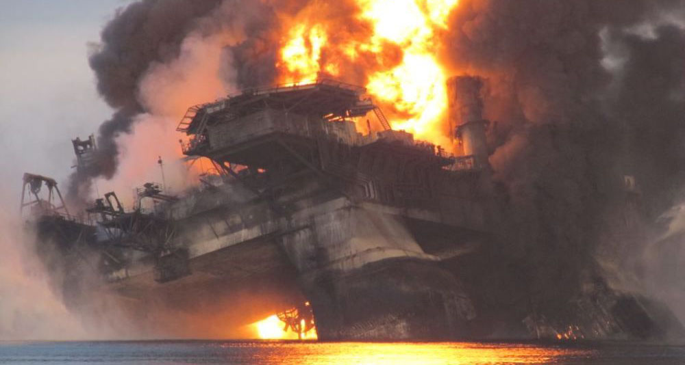
Well Control
Since 2011, Texas has experienced 78 blowouts and well control events, leading to at least 13 injuries and two deaths. In the Gulf of Mexico, 109 incidents were recorded from 1980-2011, the highest profile being the deadly Macondo disaster of April 2010. Well control events can also lead to equipment damage, environmental pollution, and loss of reserves. Evaluation of well control events, blowouts in particular, requires a highly technical analysis to understand what happened, why it happened, and who is responsible. Signa experts have testified and provided litigation support for dozens of blowout cases over the past decade, including the Macondo disaster.
Flame Retardant Clothing (FRC)
In the last two years, at least three multiple-fatality incidents have occurred at Texas oil and gas wellsites. In some cases, regulatory agencies have cited the operating company for not ensuring the use of fire-resistant clothing (FRC) by personnel. Signa has represented clients with litigation involving equipment failure, operational errors, and usage of FRC. Understanding these difficult concepts is vital for depositional and trial phases. Signa also manages projects for operators and vendors on drilling, workover, and completion projects. We provide onsite consultants who act as the operator’s representative, which gives us insight into their responsibilities and culpability during field operations.
Root Cause Analysis
To determine liability in oilfield litigation, it’s imperative to identify the “root cause” of the incident, or why it occurred in the first place. A problem-solving method called Root Cause Analysis (RCA) can be used to determine the exact origin of a problem. RCA uses a step-by-step approach to find the individual cause-and-effect sequence of events leading up to an incident. Signa uses RCA as a framework to assist attorneys in questioning witnesses and analyzing witness depositions. Frequently, there is a great deal of information that must be organized and cross-referenced. Signa uses the RCA event sequence as a basis for comparing individual witness statements. This helps to resolve conflicts by demonstrating which statements are supported by evidence. The final result is a defensible engineering opinion, supported by technical analysis and eyewitness accounts.
By Signa Engineering Corp.
©2018
Operators have traditionally used experts from several disciplines to implement Managed Pressure Drilling (MPD). Subject matter experts (SMEs) and drilling engineers create a drilling program. MPD engineers were generally utilized for design and process application. They examine objectives, determine functional requirements, and evaluate pros and cons of each MPD variation. Risk mitigation is always at the forefront. After determining the optimal MPD equipment spread, operators rent equipment from large oilfield providers, and rely on qualified service personnel to install and operate the spread onsite. The end result has historically been successful application of complex technology.
The recent downturn, however, has changed how some operators view and apply MPD.
The sharp reduction in oil prices led to significant pay cuts for some, while others were laid off or retired early. Some left the industry for greener pastures. Some banded together to start their own MPD service companies, usually by making an MPD manifold or two. The owners of these companies typically have some experience in MPD operations.
However, they often spend most of their time in marketing or management, not overseeing wellsite operations.
This shift in roles and responsibilities has resulted in a reduction of trained, experienced personnel. And it presents a possible major risk for our industry. Just because someone is listed as an “MPD expert” doesn’t always mean they have the necessary skills to apply MPD. And if a catastrophic HSE event occurs, the “MPD” name could be tarnished (especially to those outside our industry). This could lead to increased regulatory restrictions, a stall in MPD prospects, or even a setback in MPD technology.
The commoditization of MPD means cheaper prices for operators; this much is undeniable. It’s convenient to have a “cradle-to-grave” company that can provide every component that appears to solve the MPD equation. However, a large portion of these companies have limited engineering capabilities to provide complete wellbore analysis.
Equipment hands may be capable of performing computer simulations to evaluate a range of pressure scenarios. However, they might not know how to react to unknown pore pressure/frac gradient variances. They operate surface equipment to manage backpressure, but might not understand the actual implications downhole. In MPD, new formations are constantly being exposed. It might be a fracture, fault, sandstone, or tight rock.
To fully mitigate these risks, an experienced and qualified MPD engineer should be involved in every MPD project. The engineer anticipates everything downhole. They analyze formations and test their conclusions against engineering principles, then specify parameters and equipment settings.
Many operators now believe they don’t need engineering to apply MPD. They will forego hazard identification/hazardous operations (HazID/HazOP)s and downhole investigations. They don’t think about switching from conventional to MPD and back again. They don’t consider crucial elements like:
• How to kill a well during trips
• How to handle a hole in the drillstring high in the wellbore
• What to do if pipe gets stuck
• Breaking down a shoe with too much backpressure
• Rotating Control Device (RCD) pressure ratings
The real danger is operators that don’t understand (or don’t want to know) the importance of doing application engineering prior to spudding an MPD well. One anomaly feeds this misconception: Most current domestic prospects are shale, which is tight rock. Shale plays allow for limited engineering analysis because they are typically “tight” and may not flow when slightly underbalanced. Combined with a self-healing type of formation, the need for precise ECD management is greatly reduced. Since the formations are relatively passive and forgiving, these techniques and limitations will provide satisfactory results in a large majority of land-based shale projects, perhaps even 85-90%. However, the remaining 10-15% presents issues like well control (kicks), severe mud losses, and other non-productive time (NPT).
MPD is typically useful when fractures exist, but may not be really applicable for tight rock. However, many operators are running an RCD to keep gas off the rig floor. Since an RCD is being used, many consider this to be “MPD,” which leads to a false sense of security. The truth is that they have gotten lucky by avoiding negative incidents. They might not have experienced lost circulation or kicks. And even if they were underbalanced, the well typically didn’t flow because the rock was so tight. But when drilling a real MPD candidate well, many won’t know how to react to the dynamic (and potentially dangerous) environment. At the very least, operators are setting themselves up for disappointment in the technology.
Without professional engineering, service companies might try to make the drilling program fit the capacity of their equipment. This presents a significant risk. The equipment should always be made to fit the drilling program, not the other way around.
Some smaller service providers have limited equipment spreads and will try to utilize these for all their projects. Typically, they’re designed to suit the majority of passive, land-based MPD projects, but may not be the best solution for complex MPD well programs. Financially, it wouldn’t be in the best interest for the MPD service company to acknowledge any shortcomings that the equipment spread may have.
Conversely, equipment operators may bid on every MPD job that comes available, and attempt to get their entire equipment spread on the job, regardless of the application. A “complete” MPD package consists of many parts, which might be overkill.
So what’s the solution? As with most risk mitigation, the easy answer is training and use of SME MPD engineers for project design and execution. All involved personnel should have an in-depth understanding of MPD operations, both surface and downhole. They need training on the MPD process as well as equipment operation. MPD personnel need to be more than just “equipment hands.” They need to be application savvy. They should understand how to manage dynamic problems that occur during MPD. Training, combined with engineering, will result in optimal equipment and personnel placement and application engineering. The savings will easily cover the cost of the training and engineering.
For an MPD drilling program, all MPD elements should be addressed, including: planning and design, advanced hydraulic design, hole cleaning and cuttings transport, required equipment, MPD variations (Constant Bottomhole Pressure [CBHP], MudCap, etc.), hydraulic simulation, pore pressure and frac gradient variations, fluid selection, connections and tripping, and completions.
In a commoditized market, goods that have economic value – and are distinguishable by uniqueness or brand – end up becoming simple commodities. Hence, the pricing power of the manufacturer is weakened. When products become more similar from a buyer’s point of view, they will tend to buy the cheapest.
By commoditizing MPD, we are entering a dangerous phase that may ultimately hinder its adoption. MPD has been confirmed to manage difficult wells, and has become somewhat familiar to the “rank and file” of our industry. In so doing, manufacturers and service providers can provide equipment and personnel at a reduced rate.
But at what price? Is the risk reasonable?
For further information, contact Signa Engineering Corp. at 281.774.1000 or signa@44.229.100.107
By George H. Medley, Dennis Moore, and Sagar Nauduri, Signa Engineering
 Managed Pressure Drilling (MPD) has gained widespread popularity and a great deal of media coverage in recent years. By applying MPD techniques, it is possible to drill holes that simultaneously expose formations with pore pressures very close to the frac pressures of other exposed formations with minimal formation influx or mud losses.
Complex and expensive systems have been designed and implemented to maintain pressure on the wellbore using hydraulics modeling software, automated chokes and continuous surface circulating systems, often working in conjunction with one another. These systems usually require specially trained operators. This aggregation of personnel and equipment increases both the footprint and housing required, as well as substantially increasing costs.
MPD replaces the pressure exerted by static mud weight with dynamic friction pressure to maintain control of the well without losing returns. The objective is to maintain wellbore pressure between the pore pressure of the highest pressured formation and the frac pressure of the weakest. This is usually done by drilling with a mud weight whose hydrostatic gradient is less than what is required to balance the highest pore pressure, with the difference made up using dynamic friction while circulating. That sounds quite simple but has been made extremely complicated.
The big problem is maintaining constant wellbore pressure while transitioning between circulating with little or no annular pressure and shut-in with proper annular pressure to maintain balance. A great deal of time and money has gone into trying to do this with no change in wellbore pressure throughout the process. Field experience has shown that this is not necessarily cost effective, demanding an answer to the question:
“Is all this complexity really necessary?” The answer in many cases is “No.”
Introduction
As wells are drilled deeper, in deeper water, through additional and more severely depleted intervals, it becomes increasingly advantageous to be able to drill with smaller and smaller differences between pore and frac pressures that are simultaneously exposed to the wellbore. To accomplish this, lower kick and frac tolerances are necessary, as are lower margins between the actual mud weight and the pore pressure equivalent.
This allows extending casing points and, in some cases, makes the difference between being able to drill the well to the desired depth or not.
The managed pressure concept is quite simple. So long as the combination of the hydrostatic pressure exerted by the fluid column plus some other pressure is as high as the highest formation pore pressure exposed in the wellbore, the well will not flow. This other pressure can be either in the form of a circulating friction component of equivalent circulating density (ECD) while drilling or circulating, or surface pressure imposed on the annulus while the rig pumps are shut down to make a connection.
Once an accurate pore pressure is established, it is a simple matter with an accurate hydraulics model to determine what circulating friction will be and what mud weight should be used. With this done, the well can be exactly balanced while either circulating or while shut down.
Dynamic To Static
The first issue that must be addressed is how to go from static balance to dynamic (circulating) balance without either losing returns or taking a kick. This can be done by gradually reducing pump speed while simultaneously closing a surface choke to increase surface annular pressure until the rig pumps are completely stopped and surface pressure on the annulus is such that the formation “sees” the exact same pressure it saw from ECD while circulating. Note that the bottomhole pressure is constant at only one point in the annulus.
To keep bottomhole pressure constant during this transition from dynamic to static (or from static to dynamic), a variety of methods have been employed. Hydraulics models have been used to calculate a casing pressure schedule to follow while decreasing the pump rate. Computer-controlled chokes have been developed that can be employed to automate following the required pressure schedule. Circulating loops have been constructed with dedicated pumps to maintain continuous surface circulation through a choke in an attempt to make it easier to precisely control annular surface pressure.
In certain cases a conventional rig pump has been utilized as the dedicated pump, giving the added benefit of pump redundancy. Equipment has been developed to maintain continuous circulation through the drillstring during connections, thus eliminating the transition by eliminating the static situation altogether. With these methods, the well is typically never completely shut in, as any required surface pressure is imposed through a partially closed choke. All these techniques require specialized equipment that is complicated, expensive and, in many cases, unnecessary.
Transition Method
To demonstrate why these complications are unnecessary, examine a simplified case where it is not used. Instead, a simpler method, and the most basic available outside of conventional drilling, is used to trap pressure at the surface by closing the choke while simultaneously reducing circulation rate to zero, similar to that described above, but in such a way that the choke is completely closed and the well is completely shut in once pump speed is slowed to a stop.
First, a mud weight is selected that will balance the well at the desired drilling circulating rate but may be underbalanced when static unless additional pressure is imposed. Several very accurate hydraulics models are commercially available that can be run both during planning and in the field to determine ECD and bottomhole circulating pressure (BHCP) for various pump rates with the mud that is actually in the hole. These models have been confirmed with PWD data and proven quite reliable.
Using one or more of these models, either a curve or a stepwise annular pressure and pump rate table is generated for use when shutting the pumps down or bringing them on. Figure 1 shows how the annular pressure should increase as the circulating rate (pump speed) decreases for a particular situation.
All that is necessary to avoid taking influx from the well is to make sure that the annular pressure always exceeds the required, calculated pressure. It is immediately apparent that this can result in BHP exceeding the desired pressure during this transition. The question to ask is, “By how much?” and more importantly, “Does it really matter?”
To illustrate, consider a very simple, easily used technique.
A hydraulics model is used to develop a schedule of required surface annular pressure to maintain balance at several pump speeds, and each point will be reached stepwise. First, reduce the choke opening until the annular pressure reaches the next required pressure, then reduce the pump speed to the one matching that annular pressure. Reduce the choke opening until the annular pressure reaches the next required pressure, reduce the pump speed to the one matching that annular pressure, and repeat until the annular pressure is at the maximum calculated value and the pumps are stopped.
Note that the process does not result in equal increments of pressure increase (or decrease) at the end points. This is due to the way chokes and pumps function, as well as the way pressure change is exerted when mud gel-strength is broken (or, we could say, the way shear stress is affected by changes in shear rate.)
The amount by which the ECD exceeds the desired pressure with each increase in annular pressure is small and short-lived, as are any associated mud losses. If this overbalance is greater than desired – for example, if it exceeds the frac gradient – the size of the steps will be reduced until the losses are minimal. The process is reversed to bring the pumps up to speed. First, bring the pump to the first speed in the schedule. Open the choke until the annular pressure matches what is required for balance at that pump speed. Take the pump to the next speed, open the choke until the annular pressure matches what is required for balance at that pump speed, and repeat until drilling circulation rates are reached.
Again, overbalances are small and short-lived, as are associated mud losses. Even with the cost of the most expensive mud systems in use today, if this procedure is repeated every time the pumps are shut down, the cost of the mud lost can be much less than the cost of a complex computer-controlled choke and surface circulating loop system. At least as important, the equipment requirements and system complexity are greatly reduced, reducing the probability of failure.
System Disturbances
Several events may occur that cause failure or confusion when depending on fully automated computer-controlled systems. Many of these events happen as a matter of course during drilling operations and should be anticipated during planning:
• Tool joints passing through rotating control device rubber element. As the larger-diameter tool joint passes through the stripping element, the upward force exerted on the drillstring increases because the force equals back pressure at the wellhead multiplied by the cross section area of the element being stripped. As the tool joint “jumps” through the element, wellhead pressure may be lost in small increments. In more than one case, this has resulted in automatic choke oscillation as the software tries to make allowance for the pressure change. This choke oscillation then requires manual control of the choke.
• Auxiliary pump problems often result in failure to maintain constant back pressure. Again, as the automatically controlled choke valve attempts to compensate for the variation in pressure, manual control may be required. Pressure surges and vibrations resulting from inconsistent pump action require pulsation dampeners in the system at the very least.
• Equipment failure in any part of the system can force the operation to revert to manual control at any time. This occurrence must be planned for and mitigated by training the operations personnel to handle the situation.
• Contingency events of an operational or procedural nature may occur without warning that result in a change of annular pressure or of one or more components of annular pressure. While some of these can be handled easily with software adjustments, many cannot, resulting in reversion to manual control.
• Failure to calibrate software-modeled ECD to PWD tool readings or unavailability of PWD brings into question the advisability of utilizing software-controlled back pressure systems.
• Software failure or computer “lock-up” is a common contingency that must be addressed through manual application of annular back pressure. This may be as perplexing as “the blue screen of death” or as simple as power failure to the computer.
These events will be planned for and hopefully mitigated during the HazID/HazOP process, but avoidance of hazards is always to be preferred over mere mitigation. Because all these things can occur, on-site personnel must be properly trained in manual control methods even if automated systems are employed.
Lost Returns
Field experience has shown that the mud loss rate when fracture propagation pressure is exceeded is consistent. The rate of mud loss is directly related to how much above fracture extension pressure the circulating pressure is. These loss rates are manageable and repeatable. Therefore, if the amount and duration of overpressure when the fracture pressure is exceeded is very small, so are the associated mud losses.
Field experience also reveals that some of this mud lost on connections is often recovered when the BHP is again reduced below fracture extension pressure. This means is that it is often less expensive and much less complicated to manually control annular pressure with a choke to make connections when using MPD than it is to utilize software-controlled chokes and surface systems. All that is required is proper training for field personnel to correctly implement MPD with tools and equipment already available on most rigs.
In addition to a rotating head, a second choke manifold is indicated to prevent undue wear and tear on the rig’s well control equipment, but this choke manifold should be relatively inexpensive and does not require a large footprint, especially compared with the space requirements of a surface circulation loop with dedicated pumps.
Trapped Pressure vs Imposed Pressure
To demonstrate the effectiveness of this approach and its relative ease of application, the following is an example where both complex and simpler methods were applied on the same well.
The subject well was drilled in South Texas to approximately 16,500 ft. Cypress E&P employed MPD in two sections of the wellbore: 8 ½-in. intermediate hole and 6 ¼-in. production hole (approximately 11,100 ft TVD to approximately 16,500 ft). Anticipated pressure window in the intermediate hole was 17 ppg to 18 ppg equivalent mud weight (EMW) and was chosen as a candidate for MPD as much to provide personnel training and calibration of the MPD system as to apply constant bottomhole pressure (CBHP) MPD techniques.
This wellbore section allowed for practice before the anticipated pressure window in the bottom section of hole. The production hole pressure had a potentially much narrower gap (18.5-18.9 ppg). The application of
CBHP MPD to the prospect was complicated by the addition of a rebuilt drilling rig and the presence of grossly inexperienced rig crews accompanied by an attrition rate that exceeded two to three crews per week.
At the beginning of the MPD operation, the software-aided equipment package was fully operational, and approximately eight connections were made with no real problems. However, an auxiliary pump failure required that the next 37 connections be made using trapped pressure on the annulus to replace dynamic friction pressure applied by circulation rate during connections. The auxiliary pump was repaired and became available to assist in maintaining back pressure below 13,400 ft.
Figure 2 shows the time required to perform each connection vs depth. The connections made while trapping back pressure with the choke fully closed are in the shaded area between 12,200 ft and 13,400 ft. The graph shows no significant difference in the time required to trap pressure to make connections and the time required to impose back pressure using a third pump. Figure 3 shows actual back pressure applied during connections and while drilling when using both auxiliary pump assistance and when trapping pressure while the auxiliary pump was incapacitated. Again, the interval where trapped pressure was utilized is shaded in the figure.
The initial connections with the fully operational system demonstrated some fluctuation in back pressure, both upon initiation of MPD and when the auxiliary pump was reintroduced below 13,400 ft.
The data clearly show that the auxiliary pump-imposed pressure eventually can be applied more smoothly than the more manual attempts. However, even when using trapped pressure, the variation in BHP at any point below the intermediate casing shoe remained within 0.1 ppg EMW. As seen in Figure 4, the only time the BHP was not held within a 0.1 ppg EMW range was on one connection soon after the auxiliary pump was restarted and during an interval drilled near section TD where additional BHP was useful as a safety factor during connections.
Conclusions
Not every candidate for MPD can justify the cost of an elaborate, fully automatic annular pressure control system. Fortunately, a complex system is not always required, and often a more simple, historical method of controlling the annular pressure manually within a close tolerance can be employed.
While improvements in fully automated annular pressure control systems are continually being made, allowance for disruption in the operation must still be made. When disruptions occur, the same simple, historical methods of manually controlling annular pressure can be employed effectively to handle such contingency events. It is possible in most cases to adequately manage downhole pressures within acceptable limits using simple, historical, manual surface controls in lieu of complex, expensive surface pumping systems and software controls.
SPE/IADC 113689, “Simplifying MPD: Lessons Learned,” was presented at the 2008 SPE/IADC Managed Pressure Drilling and Underbalanced Operations Conference & Exhibition, Abu Dhabi, 28-29 January.